Basically there are 2 methods for buzzer control: Connecting to receiver outputs or connecting to flight controller. First method provides only basic functionality like control by a switch or activation by loss of radio connection. Second method provides additional functionality like signaling on arm/disarm, low voltage, flight modes, etc.
This is a list of different methods gathered from several forum posts. I've only verified method 4 working.
1 - Connect Buzzer to Receiver Servo Output
On CPPM mode, receiver channel outputs 7 & 8 are for PWM servo output.
- Connect this buzzer between a servo output channel and a servo like an extension wire.
http://www.myrcmart.com/rc-lost-model-alarm-findertracker-for-planegliderhelicopter-p-3145.html
- When there is no stick movement for 1 minute on Ele or Ail sticks, buzzer starts beeping
2 - Solder buzzer to CC3D STM32 pin
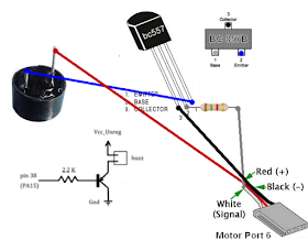
- Solder the circuit below to pin 15 of STM32 chip on CC3D board
- Setup buzzer configuration in CleanFlight configurator
3 - Use a Buzzer Enabled BetaFlight deployment
Possible BetaFlight versions:
2.1.6
Download: https://github.com/borisbstyle/betaflight/releases/tag/v2.1.6
- With this version, connect buzzer to Pin6 of CC3D output channels (motor output pins). See diagram below.
- Setup buzzer configuration in CleanFlight configurator

Active buzzer alarm modules already includes the transistor circuit above. In this case connect buzzer signal pin to motor output 6 signal pin. Connect +5v and gnd pins to a +5v source on the board. You can use any free channel output as +5v source also.
4 - Enable Buzzer on BetaFlight CLI
Possible in BetaFlight versions
after 2.1.6
Hardware Notes:
- I can confirm that Discovery Buzzer from HobbyKing works:
http://www.hobbyking.com/hobbyking/store/__14521__HobbyKing_174_Discovery_Buzzer.html
- I could not manage to make this active buzzer working with this method:
http://www.ebay.com/itm/221686970259
Setup:
- Connect buzzer to Pin6 of CC3D output channels (motor output pins) . See diagram above.
- CLI Command:
set enable_buzzer_p6 = ON
- Setup buzzer configuration in CleanFlight configurator
- Add Beeper mode in Modes tab. Assign an AUX switch as set in transmitter configuration.
- Use CLI command beeper to adjust CC3D control.
beeper -all disables all options
beeper all enables all options
Specific options:
# beeper
 beeper GYRO_CALIBRATED
 beeper RX_LOST
 beeper RX_LOST_LANDING
 beeper DISARMING
 beeper ARMING
 beeper ARMING_GPS_FIX
 beeper BAT_CRIT_LOW
 beeper BAT_LOW
 beeper GPS_STATUS
 beeper RX_SET                 ;enable buzzer control through a transmitter switch
 beeper ACC_CALIBRATION
 beeper ACC_CALIBRATION_FAIL
 beeper READY_BEEP
 beeper MULTI_BEEPS
 beeper DISARM_REPEAT
 beeper ARMED
 beeper SYSTEM_INIT
 beeper ON_USB
This is the configuration I'm using:
beeper -ALL
beeper RX_LOST
beeper ARMED
beeper BAT_LOW
beeper RX_SET
save
5 - Move SBUS channels on Receiver
For Frsky PWM receivers like X4R-SB.
This method connects buzzer to the receiver. CC3D buzzer setup is not used.
Note: X4R-SB firmware must be updated to CPPM version from:
- Bind receiver to enable SBUS and 10 channel setup. This mode can be set by connecting group 2 and group 3 pins with a jumper while powering the receiver
- On Taranis, create an input switch to control buzzer and assign to channel 9
- Connect buzzer cable to group 2 pins (+, - and signal) on receiver
- Check that there are enough AUX channels allowed in BetaFlight (v2.4.1 RC2 and newer). CLI command to set number of AUX channels is:
set max_aux_channels = xx
- On CleanFlight configurator, check that AUX9 is controlled by the buzzer switch assigned on Taranis. CC3D must be on Serial / SBUS mode.
6 - Move AUX channels on CC3D
This method connects buzzer to the receiver. CC3D buzzer setup is not used.
- Connect buzzer cable to group 1,2 or 3 pins (+, - and signal) on receiver
- On Taranis, create an input switch to control buzzer and assign to Channel corresponding to the group pins selected (Channel 1,2 or 3)
- Check that there are enough AUX channels allowed in BetaFlight (v2.4.1 RC2 and newer). CLI command to set number of AUX channels is:
set max_aux_channels = xx
- On CleanFlight configurator, change receiver channel setup from TAER1234 to 1234TAER. This will free channels 1-4 for AUX switches. Issue the following command on CLI tab:
remap 1234TAER


